




 Nederlands
.jpg)
Silver Plating Thickness for EV Charging Contacts: How Much Is Enough?

For many electrical connectors, silver plating falls within a 4–10 μm reference range. That is a useful starting point, but it is not a universal specification for EV charging contacts.
A 5 μm silver layer may be adequate for one contact and insufficient for another. The result depends on where the thickness is measured, how much contact force is applied, how often the connector is mated, and what vibration, temperature, and contamination it will face.
Current matters because contact resistance produces heat. It does not, however, translate directly into a required number of microns. The coating has to work with the contact structure throughout the expected service life.
What Does the Thickness Number Really Mean?
A drawing that states only “silver plated, 5 μm” leaves several questions unanswered.
Is 5 μm the production target, the average across the part, or the minimum allowed at the mating surface? Does it refer only to the silver layer, or to silver plus an underlayer?
These distinctions matter:
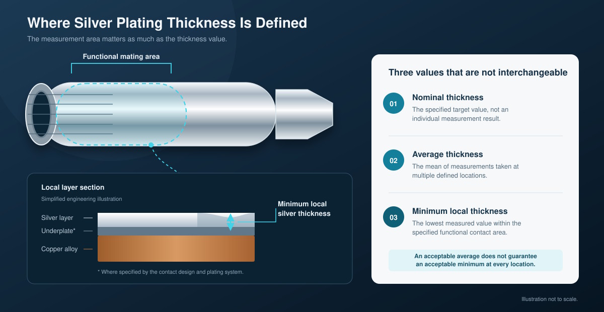
Nominal thickness is the target used to control the plating process.
Average thickness is calculated from selected measurements and may hide local thin areas.
Minimum local thickness is the lowest acceptable value at a specified measurement point.
Total coating thickness may include copper, nickel, or another underlayer beneath the silver.
For contact reliability, the minimum local silver thickness in the mating zone is usually the most useful value.
Electroplating does not build at the same rate on every surface. Edges, exposed areas, recesses, bores, and grooves may receive different amounts of metal. A part can meet an average requirement while the actual contact zone remains below the intended minimum.
The layer structure matters as well. Two contacts may both have 6 μm of silver but use different substrates or underlayers. Their adhesion, wear, and environmental performance may not be the same.
A meaningful specification therefore needs to state the coating structure, functional area, minimum local thickness, and measurement location.
What Happens If the Silver Is Too Thin or Too Thick?
Silver thickness mainly provides coverage and wear allowance. Too little reduces reliability margin. Adding more can improve durability, but only up to the point where other parts of the contact design become the limiting factors.
|
Condition |
Likely effect |
|
Too thin |
Faster wear-through, greater sensitivity to pores and local thin spots, and less margin for production variation |
|
Appropriate for the application |
Sufficient coverage and wear life without unnecessary cost or dimensional impact |
|
Thicker than needed |
Higher cost and more difficult dimensional control, without a proportional increase in service life |
When the Silver Is Too Thin
A thin coating can still pass initial contact-resistance inspection. The weakness may only appear after the connector has been mated repeatedly or exposed to vibration and temperature cycling.
Mating produces sliding and material displacement at the contact points. Even when the connector remains plugged in, vibration and thermal expansion can create microscopic movement between the mating surfaces. Over time, this movement may wear through the silver and expose the underlayer or substrate.
Local thin areas and pores become more important as the coating gets thinner. Once the underlying material is exposed, moisture or contaminants may contribute to corrosion products near the electrical interface.
The practical risk is not necessarily poor conductivity on the first day. It is losing stable electrical performance before the connector reaches its required life.
When the Silver Is Thicker
Additional thickness can delay wear-through and provide more margin against local variation. It is often useful when the contact must withstand frequent mating or demanding mechanical conditions.
The benefit is not unlimited.
A thicker layer increases precious-metal and processing cost. It may also affect contact dimensions, clearances, and mating fit. Complex geometries become more difficult to plate uniformly.
More silver also cannot correct poor contact-force distribution, unstable geometry, severe micromotion, or an unsuitable coating type. Once one of these factors controls the failure mechanism, further increasing thickness may provide little additional benefit.
Why the Same 6 μm Can Produce Different Results
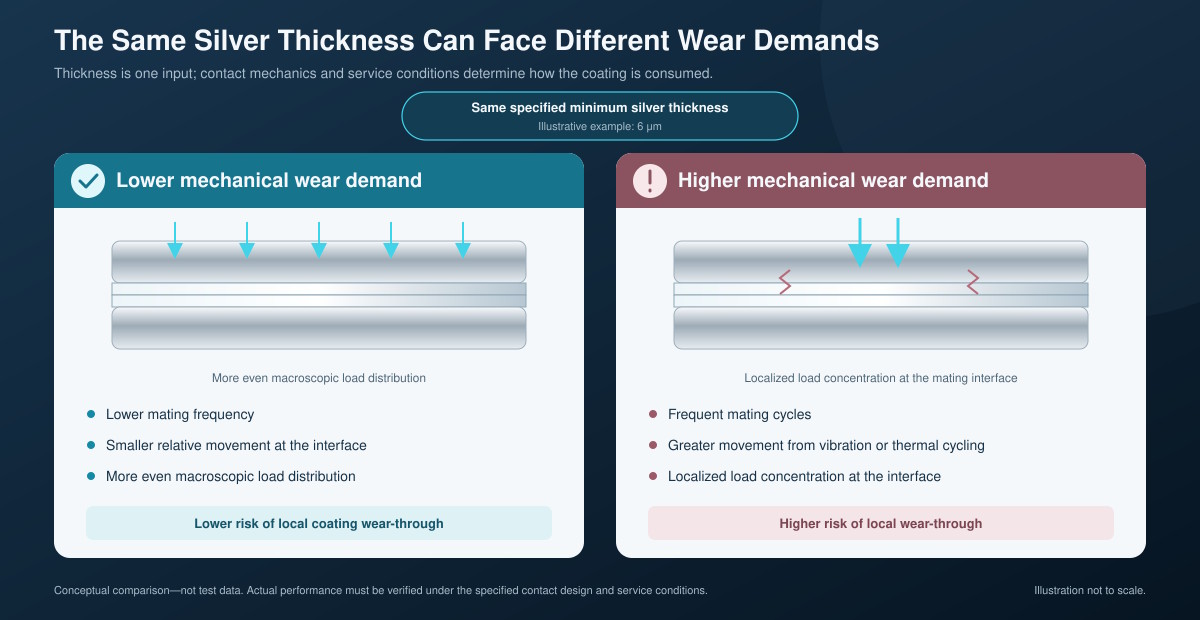
Consider two contacts that both specify a minimum silver thickness of 6 μm.
The first contact has stable normal force, controlled wiping action, limited mating cycles, and a relatively clean operating environment.
The second is mated frequently and exposed to vehicle vibration, temperature cycling, and sulfur-containing contamination. Its geometry also concentrates force in a smaller area.
The second contact has less reliability margin, despite having the same silver thickness. Improving it may require a thicker functional layer, harder silver, better force distribution, controlled lubrication, or a different underlayer. Testing may show that changing the contact geometry is more effective than adding silver.
This is why thickness cannot be separated from the mechanical interface.
What Determines the Required Thickness?
Six factors have the greatest influence on the final requirement.
1. Contact Force and Geometry
Contact force determines how the mating surfaces touch and where current passes through the interface. Higher force can help disrupt surface films and establish stable conductive spots, but it may also increase friction and wear.
Geometry controls force distribution, wiping action, contact area, and the location of the wear track. A coating that works on a broad, evenly loaded interface may perform differently on a small, highly loaded contact point.
2. Mating Cycles
Every connection and disconnection consumes some of the available coating life. Contacts intended for frequent use need more wear margin than contacts expected to remain mated for long periods.
Mating-cycle requirements should be defined before the coating thickness is finalized.
3. Vibration and Micromotion
A fully mated connector is not necessarily a static interface. Vehicle vibration and thermal expansion can create very small relative movements between the contacts.
This fretting can gradually damage the silver layer and increase contact resistance, even when the connector is rarely unplugged.
4. Temperature and Environment
Operating temperature affects contact materials, force relaxation, diffusion, and lubricant behavior. Moisture, salt, dust, and sulfur-containing gases can also change surface conditions.
A contact used in a protected indoor environment does not face the same coating demands as one exposed to outdoor charging conditions or industrial contamination.
5. Silver Type and Surface Condition
Fine silver, hardened silver, and silver alloys do not have identical conductivity, hardness, friction, or wear behavior.
A harder deposit may improve wear resistance, but thickness alone does not describe that advantage. Surface roughness and lubrication can also influence insertion force, material transfer, and coating life.
6. Production Variation and Target Life
A specification must allow for normal process variation while still protecting the functional contact area.
If the production target is too close to the minimum acceptable thickness, local areas may fall below the requirement even when the batch average appears acceptable.
The thickness should also correspond to the intended service life. A contact designed for limited mating and controlled conditions may not need the same margin as one expected to survive years of frequent use and vibration.
Do AC and DC Contacts Need Different Thicknesses?
AC and DC do not, by themselves, determine silver thickness.
DC fast-charging contacts often carry higher current and operate under more demanding thermal conditions. They may use larger conductors, different contact geometry, temperature sensors, or liquid cooling. These design differences can lead to different coating requirements.
The current type is still not the deciding factor.
An AC contact exposed to frequent mating, high vibration, weak contact force, or a harsh environment may need greater coating durability than a DC contact operating under stable conditions. Likewise, a high-current DC contact does not automatically require thickness to increase in proportion to amperage.
A useful comparison looks at:
Continuous current and duty cycle;
Allowable temperature rise;
Contact force and geometry;
Mating frequency;
Vibration;
Operating environment;
Expected service life.
Current defines the thermal requirement. Mechanical wear and environmental exposure determine how much coating durability is needed to maintain it.
How Should the Thickness Be Specified and Verified?
A practical plating requirement should answer five questions.
|
Requirement |
What it controls |
|
What is the substrate and layer structure? |
Clarifies whether the contact uses an underlayer and which layer is being measured |
|
Where is silver required? |
Identifies the functional mating zone and avoids unnecessary plating |
|
What is the minimum local thickness? |
Establishes the actual lower limit at the contact surface |
|
Where and how will it be measured? |
Makes production results comparable between parts and batches |
|
What must remain acceptable after aging? |
Connects the coating specification to finished-contact performance |
Thickness can be measured by methods such as X-ray fluorescence or cross-section analysis. The selected method must account for part geometry, curvature, substrate, and the location of the individual coating layers.
The finished contact should then be evaluated under conditions that reflect its intended use. The most relevant checks generally include:
Initial and aged contact resistance;
Temperature rise at rated current;
Insertion and withdrawal force;
Mating durability;
Vibration or fretting exposure;
Environmental aging where required.
A thickness measurement confirms how much silver is present at the test point. It does not prove that the connector will maintain low resistance and acceptable temperature throughout its service life. That proof comes from testing the complete contact system before and after aging.
There Is No Universal Best Thickness
The 4–10 μm range provides a practical reference for many electrical connector applications, but it should not be converted into a fixed rule for every EV charging contact.
Too little silver reduces coverage and wear margin. More thickness can extend durability, but it cannot replace correct contact force, geometry, material selection, and process control.
The most useful specification defines the minimum local thickness in the functional contact zone, states where it will be measured, and verifies electrical performance after mechanical and environmental aging.
Workersbee supports custom EV charging connector contacts for AC and DC charging applications, including contact geometry, material selection, and termination design.